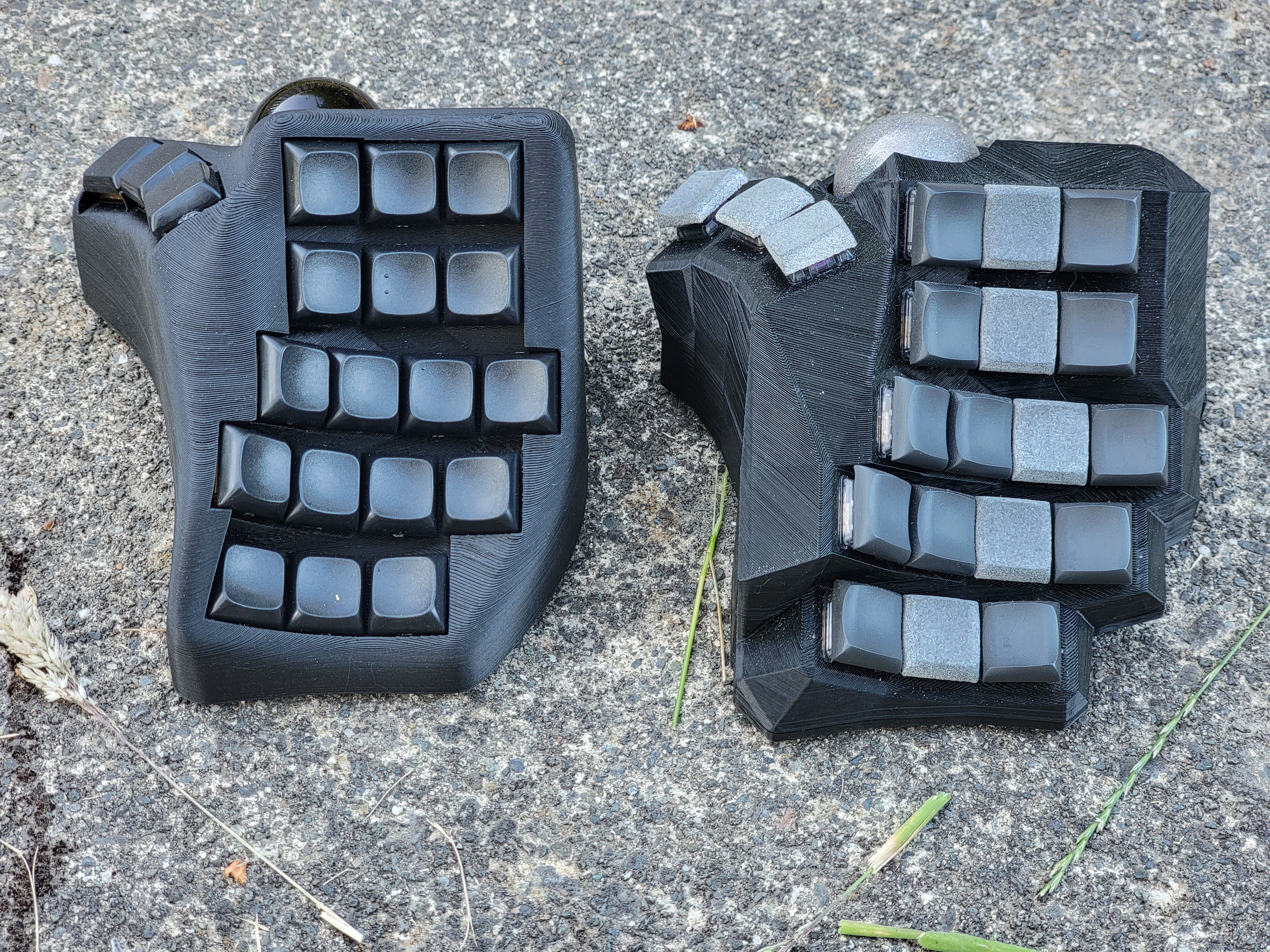
Old version in the back, new version in the front. Fresh off the printing bed. Haven’t tested it yet, but pretty happy on first inspection. Have a few sneaky features. Aiming to release it in a month or so to the community. Using it as an excuse to try out Lemmy :-)


that is pretty slick looking, what are you using the second trackball for?
edit: should have read first 🤦♂️
Needed for 4D chess.
That actually sounds super useful for 3d design. You can get 3d mice that are meant to have enough axes to get full control (can’t actually remember how), but with two trackballs you could have rotation on one and translation on the other. You’d be missing one axis of each, but you only really have two axes for each when you use a normal mouse. And all without moving your hands from the home-row, if it’s positioned well for it. I kinda want that now…
This is awesome. Great work! The track balls give me
ofFlight of the Navigator vibes.Dumb question probably, but is there a second half for the left hand?
Yes, there’s another version without a trackball. Both are designed as right side halves, and the user mirrors it in the slicer software to get the left side. This way, the trackball can be on the left side if they want, or they can have a trackball on each side, or no trackball at all. Options!
I’m just starting with all this (I’ve ordered a kit, but still don’t have it even), and this made me wonder: what’s the wiring for something like this? Is it a flexible PCB, severall small PCBs, a flat PCB with some kind of positioning adapter on the switches, just raw wires, or something else I can’t think of? And whichever the answer is, is it the same as what’s done for professionally-made ones like Kinesis’s?
There’s options for everything you listed. If you check out Bastard Keyboards, they have designed a pcb that flexes to the curvature of the columns, but as you could imagine, this is custom to the key row and column spacing. Another option is a single key pcb, often called an amoeba. There’s a bunch of variants, often with an RGB LED under the key. Even more simple is to just flywire the whole thing. The base requirement for each switch is a single diode, so there’s not much under the hood. A good practice that I’d recommend is using a hotswap socket so you can try different switch types or transfer the whole thing to another case…this is essential when developing and iterating a case such as this one. There’s a lot of options for flat split boards, and the base is often a PCB with all the traces and pads for the diode, LEDs, MCU etc. These are much easier to build, but obviously don’t have the contour foe the hands. I believe, though can’t be certain, that the kinesis uses a flexible pcb for each column, similar to the bastard keyboards.
Dang that looks crazy. With carpal tunnel I was considering building one. This is great inspiration !
Yes…that’s what got me into this never-ending hobby :-)
Super slick. Love it.
Thanks!
This is awesome! What keycaps are on both sides?
Thanks!! The one with the grey trackball has Chicago Stenos by Asymplex and the black trackball has LDSAs by Daryl from lowpro keyboards.
Awesome, thank you!!
Almost a month later, release coming?
It’s getting close… But I’m a bit hung up. I’m building the second cut using amoebas so I have a bunch of soldering to do… Trying to drum up the motivation. I figure if it’s a feature of the case, I should test it :-)
Thanks for the interest! I haven’t forgotten about it, hehe
That’s one great looking keyboard there! How did you smooth out the geometry? Looks like you started off with the usual blocky open scad design… and please don’t tell me you did that in fusion 360. I tried so many times to make it run on my Linux box and so far failed…
Super cool! I’ve been looking at a 3x5+2 dactyl, and thought about trying to squeeze a trackball in there too. This design is so close to what I envision as my ideal keyboard.
What controller/firmware are you looking at?
have you seen the Charybdis nano? its by the same guy that made that dactyl https://bastardkb.com/charybdis/
Controller will be a PI pico from We Act, the old version is using a blackpill. Under the hood, it’s running QMK. I also have an MX version in the works, actually it’s currently my daily driver, hmut there’s some small tweaks that need to be made…trackball positioning is super hard to get right.
Curious, what is it missing from your ideal keyboard? I’m open to making changes…
Fewer keys is the main one, I whittled my layout on a preonic down to 34 keys and have a ferris sweep now which I am very happy with.
I want to try some more options in terms of form factor, but keep the same key count, a 34 key dactyl was next on my list, with the idea of integrating a trackball potentially.
There are a few builds out there with the dactyl + trackball combo, but every person that makes and shares their process makes it easier for the next person, so kudos to you.
Ah OK…I have a 36 key MX variant also close to being released which is closer to what you’re after…assuming you’re OK with MX.
Beautiful!
Thanks!


